Building a Thinline Style Tele Body Without a CNC Router Machine


So, you want to build a Thinline Tele body and you don't have a CNC router machine? Piece of cake! Well, OK, probably not quite that easy. But, never despair, this web page can show you how to do it in just a few steps... uh, a number of steps... would you believe, a bunch of steps... somewhere between 40 and 100 actually. If you want to take the easy way out (not a bad idea) just go buy a thinline body from Warmoth. That'll only cost you about, let's see... uh, first you go down to the crossroads at midnight... with your first born... and a bag full of money... OK, I exaggerate. Not that their stuff isn't worth it. In fact, I used a Warmoth neck for this build (for a very specific reason). If you're strapped for cash and you just want to build a stock Tele, go hit up Guitar Fetish. Their XGP necks and bodies are as good as any and a lot cheaper than most (their pickups are also very good for the money). If you want a completely unique thinline style body though, you'll just have to build your own.

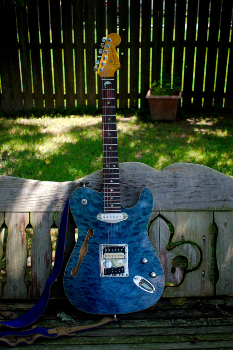
I used to build custom, neck-through guitars from scratch. Unfortunately, Katrina took most of my tools (planer, jointer, radial arm saw, etc). In addition, my back isn't what it used to be so I can't spend a ridiculous number of hours bent over a bench, building a neck, putting in the truss rod, fretting it... I eventually decided that bolt-on necks aren't inherently evil (you still may have to level and dress the frets - although the Warmoth necks are almost always just fine from the factory). The guitar I built here I call a Stelekaster. That's shorthand for Strat, Tele, Les Paul, Kiesel (formerly Carvin). I've taken my favorite features from these guitars
(in the case of Kiesel/Carvin, from a few guitars of mine) and put them together in one guitar. Oh, and a nod to PRS for the faux binding. Here's a list of the relevant features:

Strat:


Tele:


Les Paul:


Kiesel (Carvin):


Please keep in mind that this is not the cheap way out. While the basswood body blank isn't that expensive (Keim Lumber), the master grade quilted maple drop top (North Ridge Hardwoods) isn't cheap. In addition, the Warmoth neck, the Seymour Duncan pickups, and the locking Fender tuners aren't free either (those 3 things together run about $450 with shipping). If you use a standard scale neck and pickups from Guitar Fetish it would be a lot less painful. I'd still recommend the Fender locking tuners though (no, there's no whammy bar, I use these for easier string changes and tuning stability).


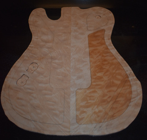
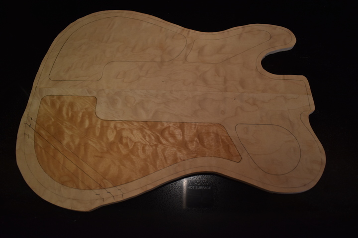
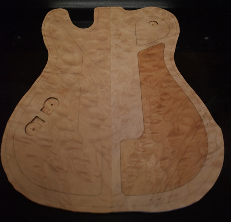
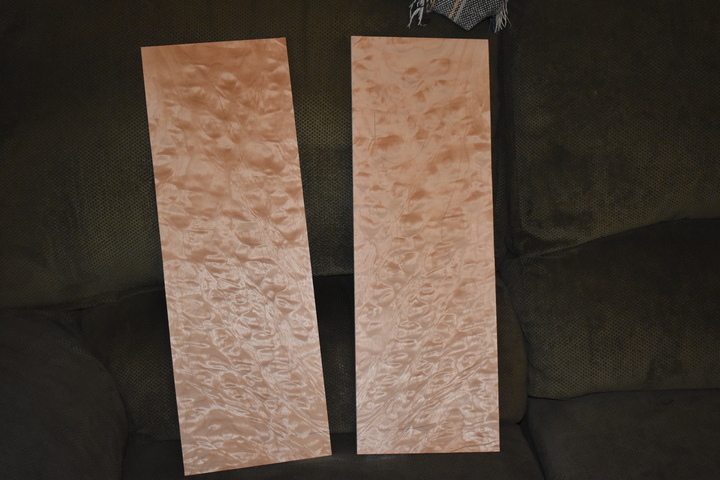
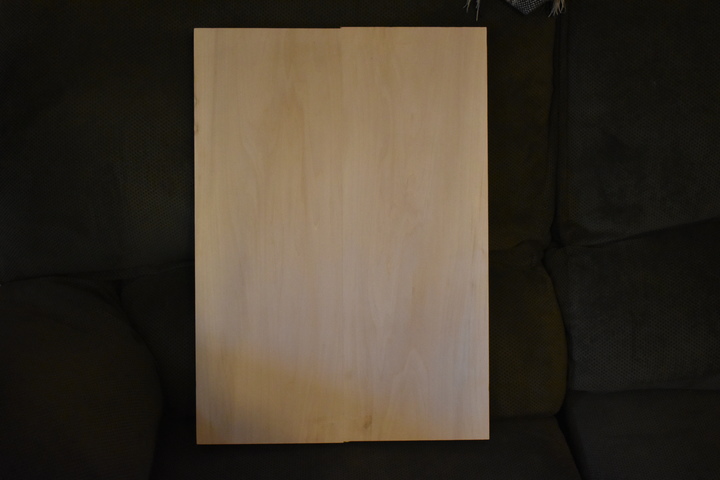
The plan here is to try to turn these (neck and hardware not pictured):

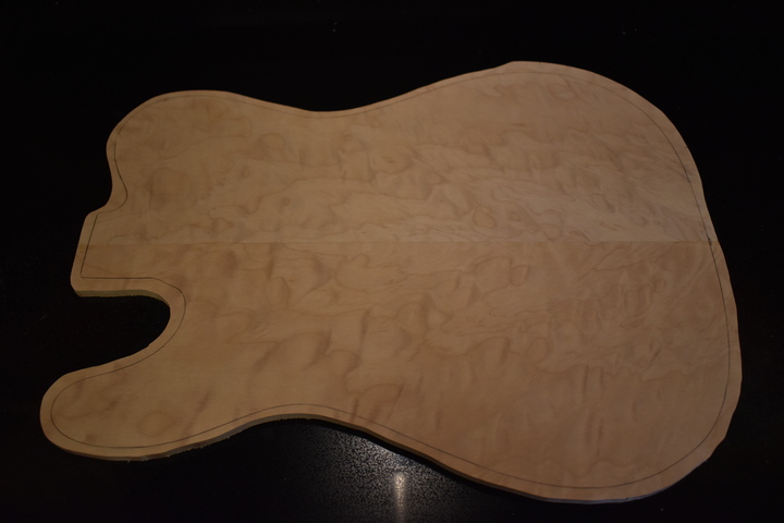
Book-matched quilted maple
              drop top pieces
Basswood body blank

into this:

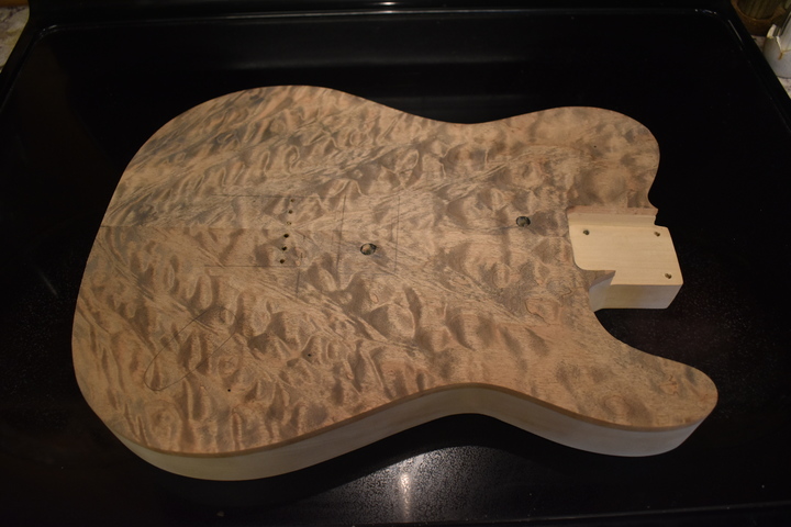
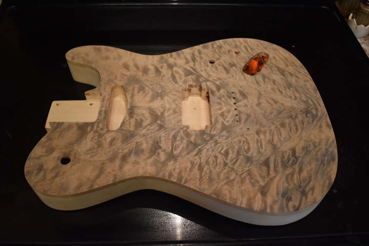
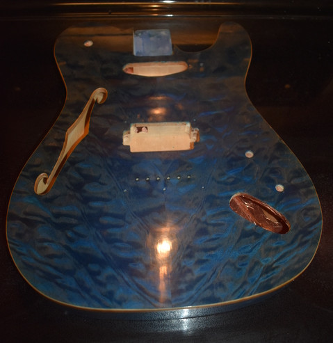
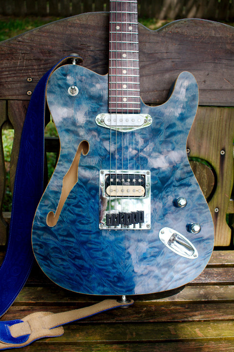
Stelekaster front view
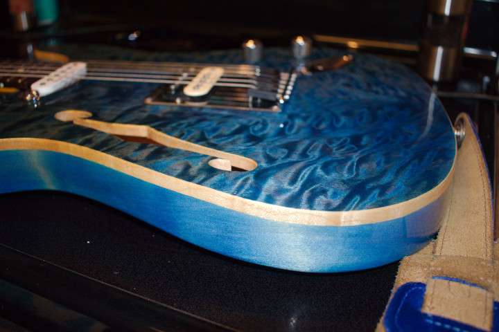
Stelekaster arm cut, belly cut,
              an f-hole
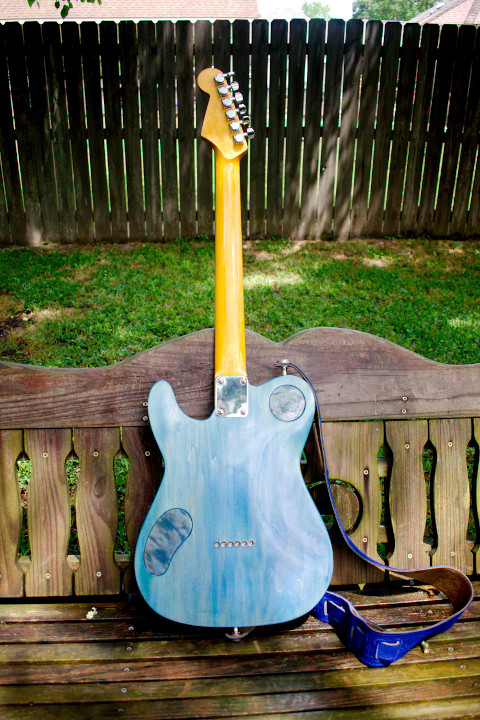
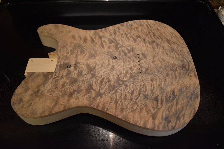
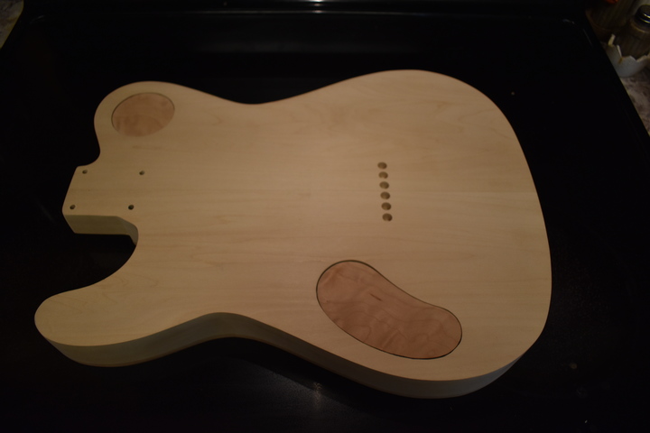
Stelekaster rear view


Building a custom guitar body is not rocket science, it just takes planning, patience, and attention to detail. If you have the tools, you can do it. If you've done any woodworking at all, most of the tools listed below (with the possible exception of the Safe-T-Planer) are probably already in your shop. Also, even though I've listed some of these tools as "essential" you could probably get by using a substitute. For example, you could use a hand drill instead of a bench top drill press but you'd probably regret it. You can get a perfectly usable single-speed drill press for somewhere between 60 and 100 dollars (mine didn't cost much more than that). The most expensive thing on the list is the router. You could use a combination of the drill press, chisels, sanding, and elbow grease to replace this but it takes a lot more work (and a lot more care). Do yourself a favor and at least get a drill press and a router, you'll use them many more times in the future.

The pictures below are not always exactly associated with the accompanying text but are used to illustrate the most important point(s) of the text (I didn't have time to take a picture every time I did a single operation). IMPORTANT NOTE: Read through this whole thing a couple of times before you start so that you can wrap your head around what you're planning to do. There's also the possibility that I have something out of order ;-)


First, you need some essential tools:
  • Bench top drill press (This doesn't have to be large or expensive but you need to add a plywood or mdf table to it. The table doesn't have to be fancy, you just need more room to hold the guitar body).
  • Go to Klingspor's Woodworking Shop and get the Robo-Sander™ Flush Trim Sander set (yeah, it's expensive but you'll thank me later) or at least the 2"x2" (it will handle almost all of the body).
  • Router (I like the palm routers with separate plunge and fixed attachments but any simple router will work).
  • Dremel tool with router base (I definitely recommend StewMac's metal precision Dremel router base over the Dremel branded plastic one, but either will work. This too can be replaced with a drill press, some chisels, sandpaper, and elbow grease).
  • Random orbit sander (I don't recommend trying to hand sand this project but, hey, it's your arm).
  • StewMac Safe-T-Planer (for $15 extra, Keim Lumber will plane the blank to 1 1/2" so you wouldn't need this but, trust me, you'll love it).
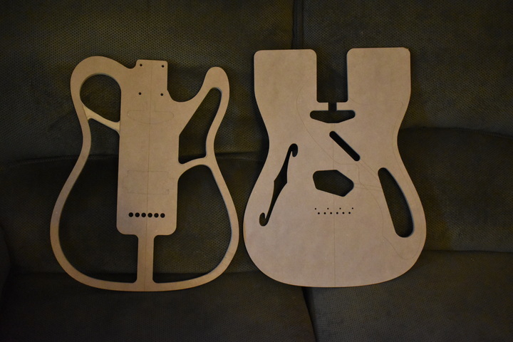
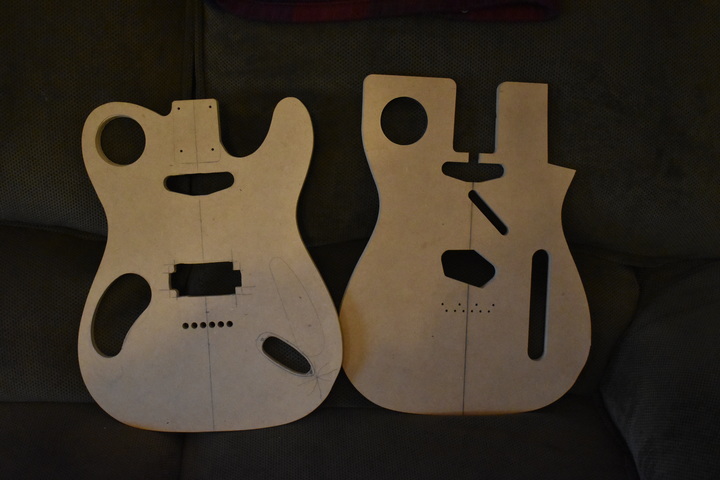
  • Templates (my recommendation is Javelina Guitars but you could search the web for Fender templates and make your own). In the picture to the right, note the extra cross piece on the upper bout. I added this so that I could isolate the Les Paul style switch from the f-hole chamber. If you're not going to do an LP style switch, don't worry about it. I also removed the thicker section of the lower bout where the standard Tele jack goes since I used a Strat jack on this build.
  • Clamps, clamps, clamps. Oh, and some more clamps (I really like the Irwin QUICK-GRIP clamps).
  • Drum sander drill bit(s) (2" long bits are good for sanding in the bouts).
  • Set of graduated length, top bearing, flush trim router bits.
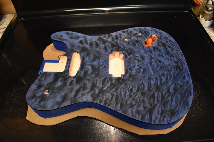
  • One bottom bearing flush trim router bit (3/8” is best).
  • A good set of forstner and/or brad point drill bits.
  • 2X5mm neodymium magnets.
  • A 5mm brad point drill bit, if you don’t already have one.
  • Dye - I can recommend Transfast, Transtint, and ColorTone water based (powder or liquid). I've used all of thge above, although I used Transfast powders for this.
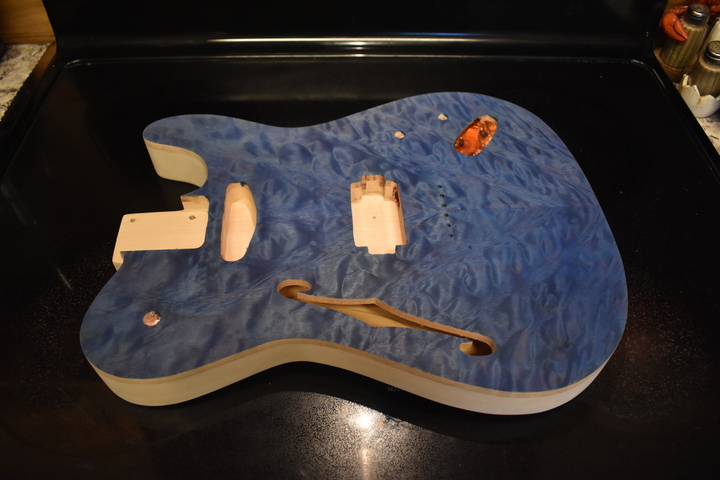
  • Tru oil (I'll explain this later) and wipe-on water-based gloss poly (Minwax is what I used)
Javelina
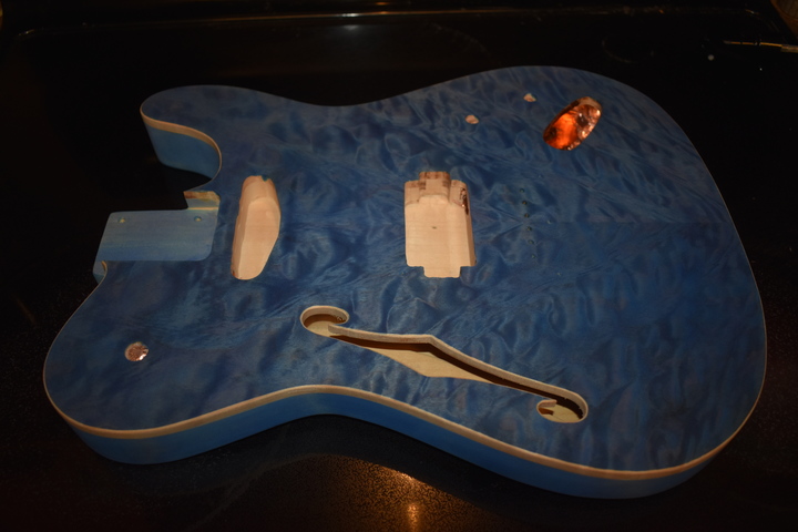
                thinline body templates
Some non-essential, but darn helpful, tools:
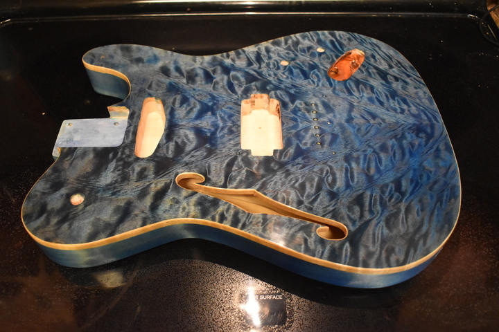
  • Bench top band saw (a jig saw will do but it’s much easier on a band saw).
  • Scroll saw (again, a jig saw will work but it's harder).
  • StewMac 1/8” upcut Dremel router bit (if you’re going to do any inlay work later I would also recommend the 1/32” bit). I think the equivalent might be available elsewhere online but I haven't tried them.
  • Small and medium sized 120 grit flap sander bits for Dremel (unless you like doing hand sanding in tight areas - like inside the horn).
  • Dremel sanding drum bit(s).
  • Oscillating Drum sander.
  • Some spare templates or mdf/plywood to make other templates. This is needed if you're using non-standard things like humbuckers, custom cavity plates, Les Paul style switch, Strat style jack plate...
Spare body blanks for making templates
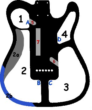
So, here we go... The diagram on the right will be referred to throughout this web page. There are links back to the diagram but it might be easier to print out the image (hint: right click on image, Save Image As..., then print it).

Make the control cavity cover templates for chambers 1 and 3 out of 1/2” MDF or plywood. Make them any shape you want, I used a circular cover for the switch cavity but you're better off using some other, non-symmetrical shape so that you never have to wonder which way it goes on.

Make sure that you don’t make the chamber 3 control cover so large that you won’t have enough quilted maple top wood left (after cutting out the top) to make the cover. You don't have to use the quilted maple but it sure looks good.

If you’re going to use a Stratocaster jack plate you also need a template for that (I cut one in one of the spare templates).
Thinline layout
                diagram

1

Align and attach the top body template (the one without the neck pocket) to the top of the body blank with 2 screws (in the pickup and/or neck pocket locations - I used drywall screws). Make sure you’re in the location of the bridge, bridge pickup, neck pickup, or neck pocket because later you’re going to rout these in the top and you don’t want to miss and leave a hole in the top! Not that you'd be able to see it because it will be covered by the drop top (or the bridge). However, later on, we're going to drill through the drop top in the same locations. In this case, I used the front pickup location, but I should have used the center of the neck pocket since that will definitely be covered.

Draw the outline on the body blank, detach the template, then band (or jig) saw the rough outline of the body from blank. Get as close to the template edge as possible. I didn't do such a wonderful job here but I went back and got it closer (I just didn't take another picture).
Body band-sawed with attached top template

2

Safe-T plane the top of the body blank down by 7/32” (if you paid your body blank supplier to plane the blank to 1 1/2" you can skip this step).

Sand the top of the body blank down by 1/32” with 120, 220 grit (random orbit sander - carefully so as to keep it level).  A little trick I use is to find a very flat surface (in my case my bench), stick some 120 grit sandpaper (I can recommend the Dura Gold sandpaper rolls) to the surface, draw some random pencil lines on the blank surface, then wear your arms out scuffing the blank over the sandpaper.  Once all the lines are gone the surface should be absolutely flat.

Reattach the top template to the top of the body blank, then Robo-Sand the outside of the body to the template.  This will always leave about a half millimeter of excess wood outside the template but it's probably a good idea to leave it and then hand sand it later (because it will get little dings in it while you're working on it).  If you don't have the Robo-Sanders you can rout the outside of the body blank to the template using graduated length, top bearing, flush trim router bits. Go very slowly and watch the grain direction! You can easily take a chunk out of it when going against the grain.

Mark the chambers, 1 through 4,  on the top, then remove the top template.

Mark the belly cut area (2a) on the top of the blank so you can avoid routing it too deep.
Body blank routed to shape after planing

3

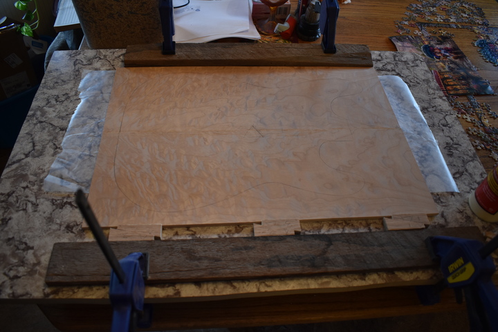
Glue the book-matched, top blank together (methods vary, the best I’ve seen is J. S. Bogdanovich’s method: https://www.jsbguitars.com/learn-guitar-making-techniques/plate-joining/ ). Note the little wedges in the bottom of the photo on the right. I got that from Bogdanovich. Like Jimmy Buffett (and/or Lord Buckley) said, "it was so simple, like the jitterbug, it plumb evaded me". You don't really need an excessive amount of force to glue these together so the little wedges provide plenty of pressure.You can also put a strip of wax paper across the top and clamp a very flat board over the seam to make sure it's flat.
Book-matched drop top pieces being glued
                together

4

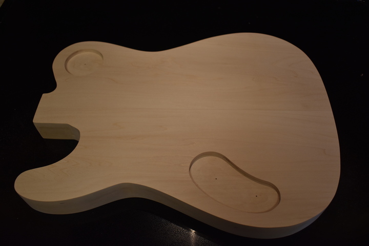
Attach the drop top blank to the body blank top.  I mark the holes from the body template and then drill the same holes in the drop top blank.  You can also use double sided tape if you prefer.

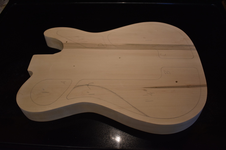
Draw the body blank outline (backwards, obviously) on the back of the top blank and rough cut out the top using scroll, band, or jig saw. Allow a little more in the area near the arm cut, 2b, because it will be closer to the body edge when bent).
Rough cut drop top from back

5

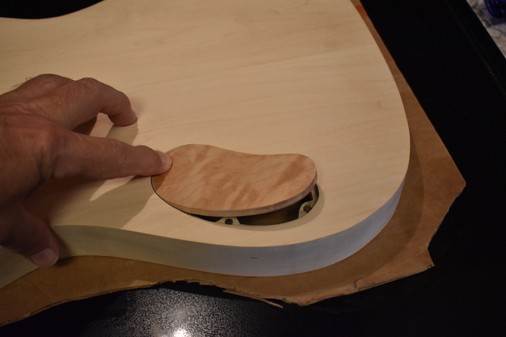
Now you can make the chamber 1 and chamber 3 control cavity covers from the excess quilted maple (actually, you can use anything you want but the quilted maple looks good when it's finished).  If you keep them small enough you can use the same wood as the body.

Use the templates you made earlier to draw them on the maple (or whatever) then use a scroll (or jig) saw to cut them out. Make them just a touch large so that, after you cut them, you can sand them to the actual shape on your drum sander or drill press using a sanding drum bit.

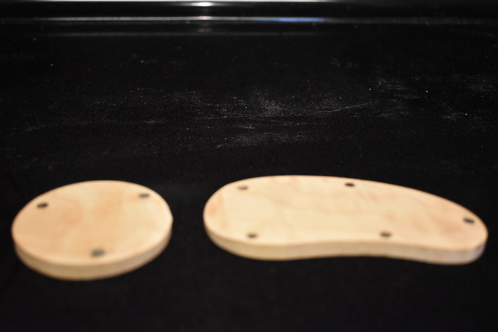
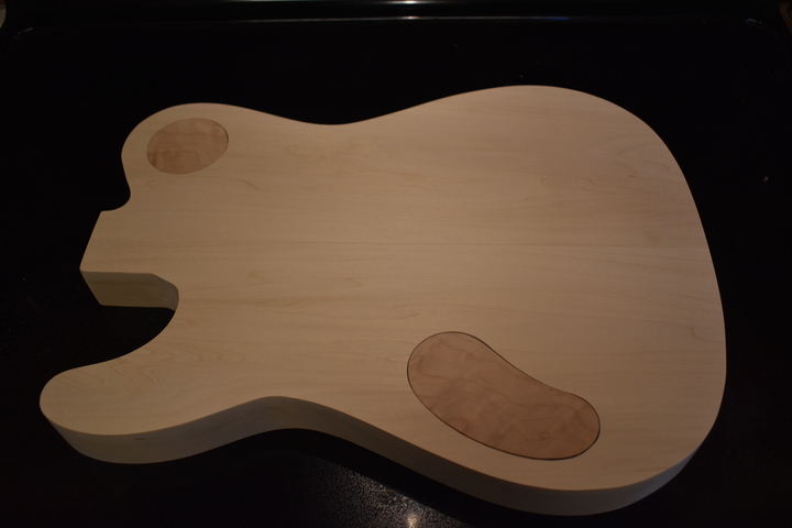
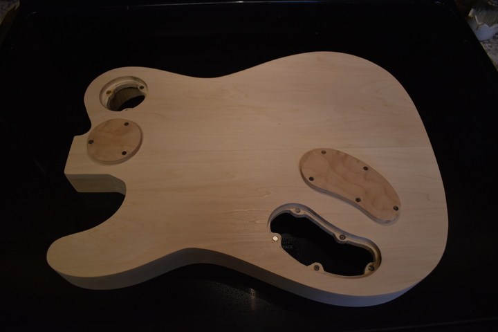
This picture is from later in the process (note the magnets and the beveled edges) but you get the idea.

IMPORTANT NOTE: Don't make either of them symmetrical.  Making this one round was seriously dumb since you have to try to figure out which way it goes back in every time you use it.  Needless to say, this was the only one I ever made symmetrical.
Control cavity
                covers

6

Drill holes at locations A, B, C, and D. I used a 1 3/8" forstner bit. Whatever bit you use make sure the deepest part only goes down to 1/4" from the back. These will be pilot holes for routing.

The easist way to do this is to make a cavity template out of MDF, screw it to the body blank (using the aforementioned holes), then rout it, but you can free hand it if you want because nobody will ever see the inside.  I used a template for the one in the picture. 

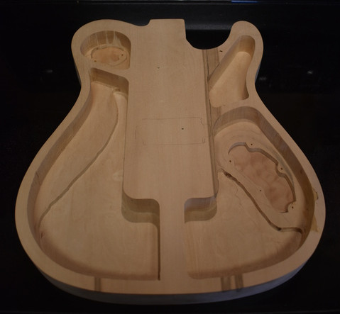
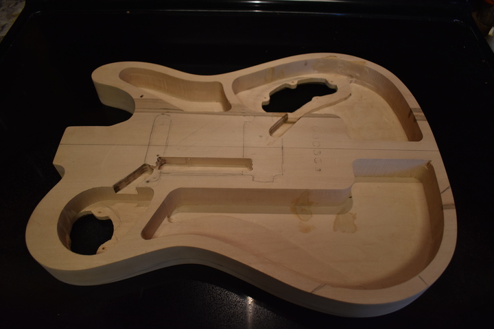
Rout all chambers to depth needed for inside of belly cut area (2a - you have to estimate this - remember, you can always take out more but it's very difficult to add wood). For this build I used 1/2" from the back. Unless you make a very pronounced belly cut this will probably be adequate. This is the figure used in the following router instructions, YMMV.

Rout chambers 1 and 3 to 1/2” from bottom of body blank (which better be 1” from the top of the blank).

Rout chamber 4 to 1/4” from bottom of body blank (which should be 1 1/4” from the top of the blank).

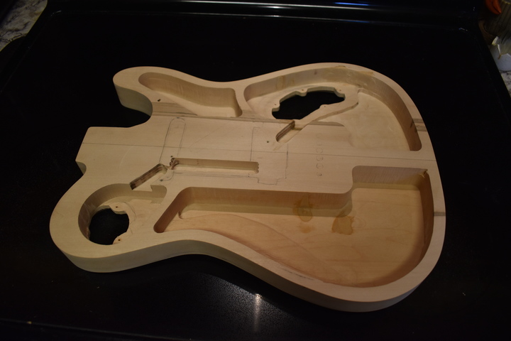
Rout chamber 2 (not including 2a which you have to draw and then rout freehand - good luck) to 1/4” from bottom of body blank (which should be 1 1/4” from the top of the blank), then detach the template.
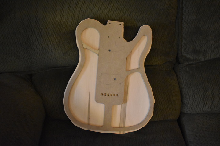
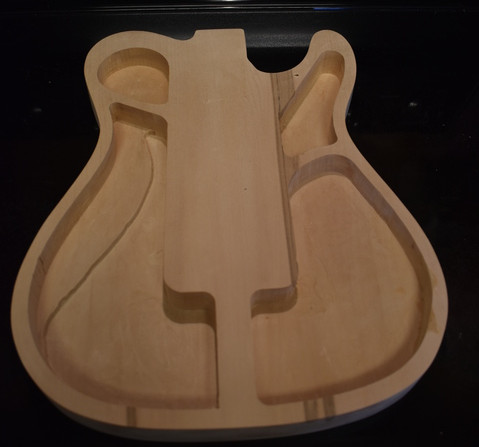
Body blank
                with routed chambers

7

Mark approximate (but, hopefully, fairly accurate) locations for the Les Paul style switch and the volume and tone controls inside the body in the bottom of chambers 1 and 3. Drill a tiny hole at each of the 3 locations.

Center the chamber 1 (Les Paul style switch) cover plate template on the back of the blank at the tiny switch hole, double side tape (and/or clamp) it in place, and rout down 1/4” (or maybe just 15/64”).

Position the chamber 3 (volume/tone and jack plate) cover plate template on the back of the body blank, over the holes (by eyeball and/or any other way you can think of to measure it), double side tape (and/or clamp) it in place, and rout down 1/4” (or maybe just 15/64”)
Back
                control cavity recesses routed

8

Sand the control cavity covers to the lines (that you drew from the templates before you rough cut out the covers). Don’t forget to constantly check them against the control cavity routs on the back of the body. As mentioned above, use a drum sander (or a drum sander bit in the bench top drill press) to slowly sand down to the lines.
Back control cavity routs with sized covers

9

Drill through from back of chamber 1 in the center of the chamber 1 cover plate rout. Use a bit that is large enough to get your scroll (or jig) saw blade through.

Drill through the approximate middle of the chamber 3 cover plate rout.

Using a scroll (or jig) saw cut the internal bounds of the chamber 1 and 3 cover plate routs into the back of the body (5/16” from edge of rout). Leave little bumps for where you want to locate the 2x5mm neodymium magnets that we’re going to use to hold the plate on.
Control
                cavity openings from inside

10

At this point you can install the 2x5mm magnets. Use a 5mm brad point bit to drill the recesses in the body blank (DO NOT DRILL THROUGH). The brad point bit will leave a tiny indention in the bottom center of the recess. Use a 1/16” drill to drill through the indention into the body cavities.

IMPORTANT NOTE: Make sure that you leave one end of the cover without magnets.  See the next section for the reason.

Place the cover plates where you want them and then use the 1/16” bit (pushed through the hole from inside the body) to mark the location of the center of the magnet recesses on the cover plates.

Drill the matching recesses on the cover plates (DO NOT DRILL THROUGH or you’ll hate yourself in the morning).

Using super glue, glue the magnets in the recesses in the body (it doesn’t matter which way you set them unless you have a symmetrical cover plate (like a circle, bad idea) in which case you’ll want to make sure that the polarity of one of the magnets doesn’t match the others so that the cover plate will only go on one way. This is why you shouldn't use symmetrical cavity covers.

Place a magnet on each of the magnets in the body (don’t worry, they will orient themselves). Pull one magnet off (you’ll need needle nose pliers), flip it over, and glue it into the matching recess on the cover plate. Wash, rinse, repeat.
Cover plates and recesses with magnets installed

11

Sand a beveled edge into the underside of each of the cover plates at a strategic location between two of the magnets. Experiment to find a good location. This will allow you to press on the cover plate over the beveled edge to lift the opposite edge so that it can be removed.

You could, instead, place a large magnet in the center of the underside of the plates and then make a magnet tool to lift the plate (this is how C
rimson Guitars does it - BTW, you should watch that guy's videos, they're great). The problem with this method is that you have to inlay the magnet at least an 1/8” into the bottom of the plate and you would have to carry around a magnet tool to remove the cover plates. We're following the KISS principle here - Keep It Simple Stupid.
Cover plate with beveled underside edge

12

If you want to save a tiny amount of weight you can rout the area of chamber 3, about 1/2” away from the cover plate opening, down to 1/4”. I don’t know how much weight this saves and it may not be worth the effort. It’s certainly not worth doing in chamber 1.
Chamber 3 excess routed down to 1/4"

13

Rout the wiring channel (5) from chamber 1 to the neck pickup cavity location (approximate location, since the pickup cavity hasn't been routed yet).

Rout the wiring channel (7) from the neck pickup cavity to the bridge pickup cavity location (again, approximate).

Rout the wiring channel (6) from the bridge pickup cavity location (ditto) to chamber 3.
Wiring channels
                routed

14

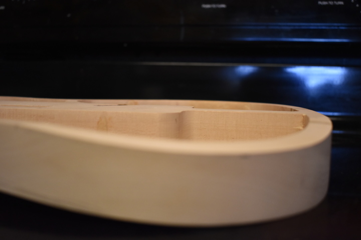
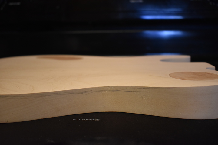
Somehow shape the arm cut (2b), which you have to freehand based on personal preference... and how far you think you can bend 1/4” quilted maple... and round the edges (where the top meets the blank on each side of the cut) a bit because you have to bend the top and it won’t go at an acute angle.

I used a belt sander to do this but I’ve seen one guy on YouTube who built a band saw jig... of course he had a honking big band saw. Obviously, you can’t do this with a bench top band saw.

I finally ended up making an angled jig that I can use with the Safe-T-Planer to do this.  Double side tape the body to the jig then (keeping it perfectly straight,I used a piece of straight wood clamped to the drill press table) slide it under the Safe-T-Plane to take some off.  Move the straight edge, was, rinse, repeat.
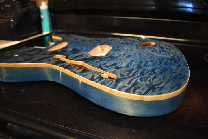
Arm cut from the side

15

Using whatever method works best for you, make the belly cut. I usually just use a random orbit sander and 60, 120, 220 grit (I do a very modest belly cut - since I have a very modest belly). If you prefer, you can use a surform or rasp or axe or ninja sword or chainsaw or a very well trained beaver and then smooth it out afterwards.

IMPORTANT NOTE: You don't want to go too deep. Remember that you only have the shelf that you left when routing the interior (the 2a area) to keep you from going through.
Belly cut marking and beginning of cut from side

16

Smooth out the interior of chamber 2 and finish with a few coats of wipe-on poly or spray paint it flat black (this area will be visible through the f-hole and also will be open to moisture). If you want, you can also stick your logo decal and a date just below where the f-hole is located (just like the professionals!).

Interior of chamber 3
                with light poly coat

17

Position the top template over the back of the top blank. Although you may have taken some off the sides when sanding, the ends of the blank (at the neck pocket and where the end strap button is) are end grain and shouldn’t have lost much wood to sanding. All you have to do is align the top template center with the center stripe of the body blank and then move it to match the bottom at the end strap button location.

Now, draw the outline of all of the chambers on the back of the top blank. You also need to mark the locations of the 2 screw holes that are in the top template. These MUST be in the bridge/neck pickup and/or neck pocket locations so make sure you get them right (which you should have done when you drilled the holes for the template - otherwise you’re going to be buying yet another expensive piece of wood to replace the one you just ruined).

Lesson learned recently - don't try to re-use the holes, drill two new holes near the existing holes. That way, you don't have to worry about getting the locations exactly right.

The back of the top over chamber 2 needs to be sealed with a few coats of wipe-on poly, try not to put it on places that will be touching the gluing surface of the body blank - don’t forget about the arm cut bend making it, effectively, shorter. The easiest method is to mask it with tape and spray it (preferably with flat black paint).
Underside of top plate with poly coat in
                chamber 2 area

18

Mark the location of both ends of the arm cut on the underside of the top blank (where the top meets the body in the middle of the curve that you put in to allow the maple to bend). Also mark the end of the curve on both sides (i.e. where it goes back to flat). Draw a line between the arm cut marks on the underside of the top blank. Draw two more lines, one on each side of this line, parallel to it and about 1/8" inch away.

Underside of top with marks for routing
                bend relief

19

Now, drill tiny pilot holes in the top plate where you put the 2 marks for the top template screws. BE SURE YOU’RE IN THE RIGHT LOCATION!!! These should be directly over the screw holes in the body blank where you screwed down the top template (in the bridge/neck pickup and/or neck pocket locations). Put toothpicks through the holes and line the top plate up over the body blank holes. If they are in the correct locations, drill the correct size holes for the screws and countersink them into the top of the top plate.

After you’re done making the holes, screw in the screws and double check that you did it right.

From the top locate where you want your volume and tone controls (you should have already kind of figured this out so that the control cavity will be in the right place) and drill tiny holes through the top at these locations (exact locations, not approximate).

From the back of the body blank (through the chamber 1 control cavity hole), mark the location of the dead center (as they say at the Haunted Mansion) of the Les Paul style switch. This may not be the dead center of the control cavity cover or chamber 1 (in fact, it’s probably not, so measure it just to be sure). You might want to mark it from the top to get it exactly where you want it. Just make sure you have enough room around it in the cavity to mount the switch.

Take the top off the body blank and drill a tiny hole though the top at the location of the Les Paul switch.
Underside of top with routed control recesses

20

 
Here's a fun thing to do - order long shaft pots so you don't have to recess the volume and tone pots.  Get pots with at least 9.5mm of threaded shaft.  As far as I can tell, no one makes long shaft Les Paul style switched so you still have to recess that.

Use a Dremel router to cut the recess for the Les Paul switch and, if you only have short shaft pots, the pots.

IMPORTANT NOTE: Try it on a scrap piece first. Once you have gotten the router set at the correct depth you can duplicate this on the back of the top - DO NOT DRILL THE CENTER HOLES IN THE TOP - you’ll do that later, from the top, with a brand new brad point bit so you don’t get any tear-out.
Underside of top with control locations routed

21

Using a Dremel router, rough cut a slot 1/8” wide and deep along the center of the center arm cut line (DO NOT CUT ALL THE WAY TO THE EDGE, stop about 1/4” short of the edge, you don’t want to see this on the outside). Rout the other two parallel slots as well. These are also 1/8” deep and wide and you also DON’T WANT TO CUT ALL THE WAY TO THE EDGE, duh.

You can clamp a straight edge of some sort to the top to use as a guide.
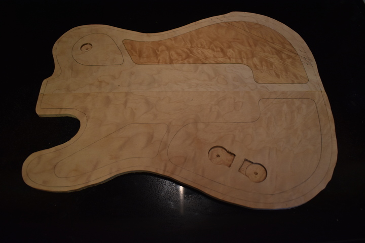
Arm cut relief routs with some copper foil
                shielding altread done

22

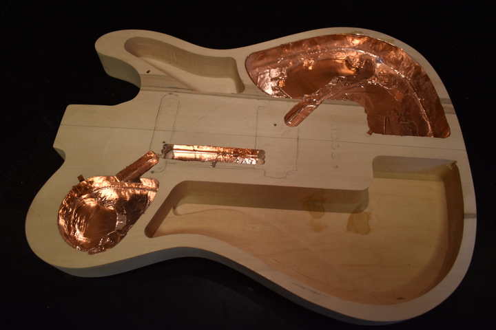
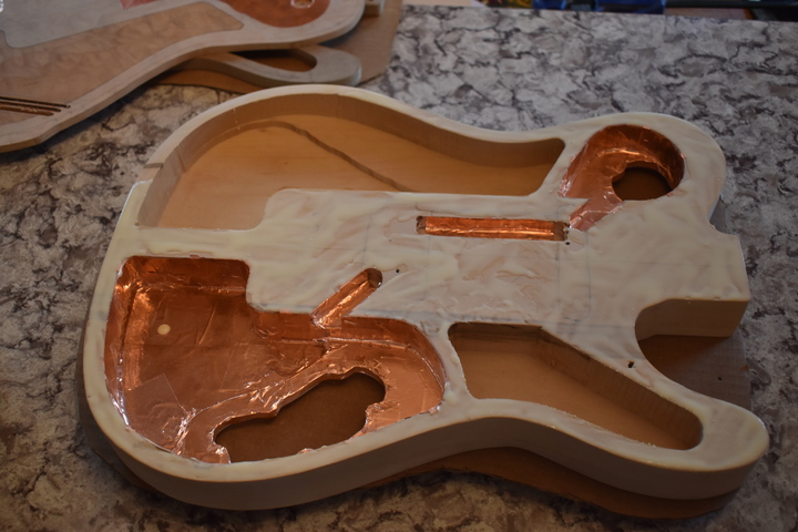
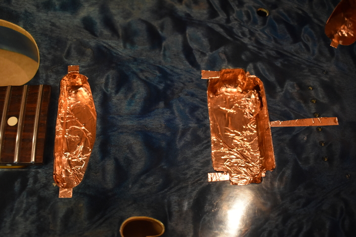
Using copper foil tape (don’t use that crappy paint, it’s not a good conductor - check it with an ohm meter if you don’t believe me), shield chamber 1, chamber 3, and the wiring channel slots.

In chambers 1 and 3 run a copper foil tab from the inside of the cavity to cover each of the magnets on the inside of the cavity recess. This way, when you’ve put copper foil tape on the inside of the cover plates, there will be contact between the foil coverings inside and outside of the cavities.

Also, shield the underside of the cover plates.
Inside of body,
                shielded

23

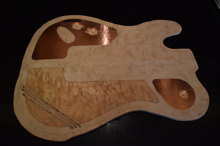
Shield the underside of the top where it will be over chamber 1, chamber 3, and the wiring channels (do not go over much of the gluing surface but you need to at least go a little way in to create a complete Faraday cage). Do not shield the recesses for the switch and the volume/tone pots. You’re going to drill through those later and then you can shield them with a small piece of copper foil tape.

If you are going to install a Strat jack, mark the area where it will be and leave about 1/4” bare around it. You can shield that later, after you rout it.

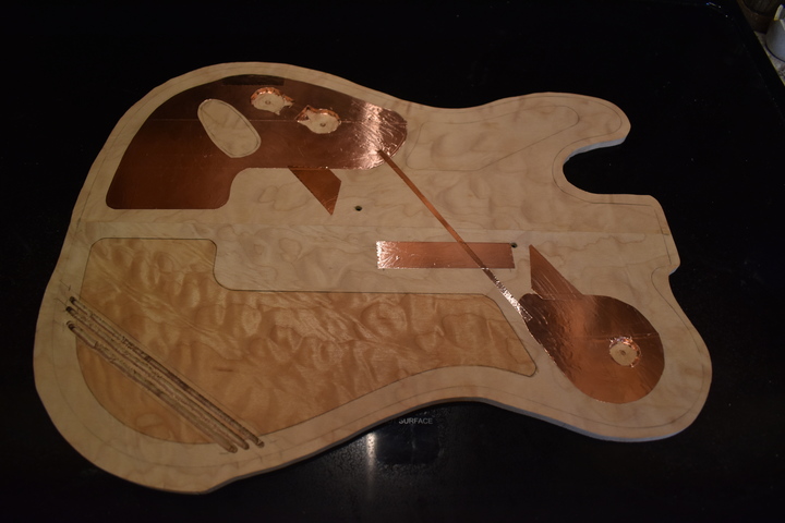
If you’d like you can run a very narrow strip of copper tape on the bottom of the top plate. This should be run from the copper foil over chamber 1 to the copper foil over chamber 3, avoiding the pickup locations. This just provides another ground from chamber 1 to 3. You can check it with an ohm meter to make sure it’s doing what it’s supposed to do.
Underside of top, completely shielded

24

IMPORTANT NOTE: If you're not using a Strat, top-of-body jack plate, you need to drill the hole in the body blank (for whatever kind you're using) now.  That way you can fix the copper tape shielding prior to gluing the top to the body.

Time to get ready to glue stuff together! First, get your top template and your other template (with the neck pocket) because you’re going to use them as clamping cauls for the top and bottom, respectively.

You also should cut out a couple of cardboard guitar shapes to use as cushions between the templates and the top/body (I have a few of these around and they’re very handy for avoiding scratches and dents).

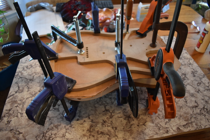
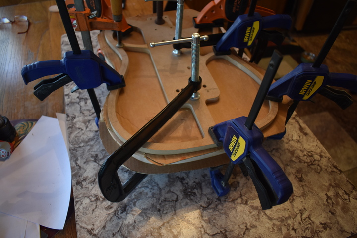
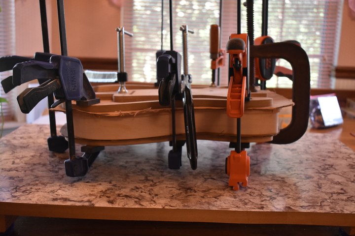
You are also going to need approximately one bazillion clamps (roughly equivalent to a metric butt load of clamps). A couple of deep throat clamps will help the screws with the middle of the top.
Clamping dry run

25

Before you put glue on anything, dry run the entire clamping procedure first. What you’ll probably find is that something doesn’t fit. After you’ve got everything ironed out, remove the clamps and cauls then proceed to the next step and do it all over again.
Clamping dry ryun

26

Cover the gluing surfaces on the top of the body blank with your glue of choice (I prefer Titebond original wood glue). Don't put ANY glue in the arm cut area. This has to be perfectly flat and clean so that it will glue up correctly later on.
Top of body blank
                coated with glue

27

Position the top over the body blank and screw in the 2 screws (spray the screws with PAM or WD-40 first so you can get them out after the glue has dried).

Put your cardboard body shape shims on each side of the top/body.

Use the top template (the one with the chamber routing pattern) as the top clamping caul (that way you will only clamp where it is needed and won’t be pushing down over a chamber).

Use the other template as the bottom clamping caul. Then, using the aforementioned bazillion clamps, clamp the top to the body blank. Don't clamp at the arm cut. Go around the body and wipe up any excess glue that gets squeezed out.
Top clamped to body

28

After the glue has completely dried (I’d wait about 3 hours), remove the clamps and the 2 screws.

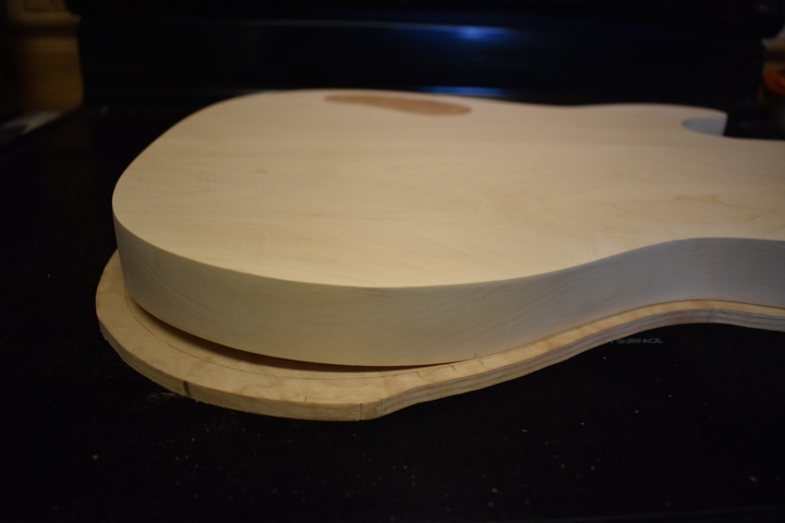
Leave it for at least 24 hours before clamping the arm cut. You can place the wet cloth on it and let it soak but you really want it to be completely set before you put that much pressure on the wood.
Top and body
                glued, showing arm cut gap

29

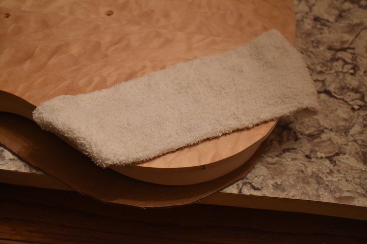
Place a very damp cloth over the arm cut where it’s going to bend (essentially, directly over the underside arm cut slots) and leave overnight (you can wet it occasionally if it dries out too much).

IMPORTANT NOTE: Try very hard not to get any part of the body blank wet.  Usually the body blank is softer wood like basswood, poplar, mahogany, or alder.  If these get wet they will swell.  Thanx and a tip of the hat to my own impatience!  Been there, done that, got the T-shirt.

In the morning, remove the cloth and test to see if it will bend easily enough without breaking. If it is still too stiff, try using an iron (set on high) over a wet cloth. Press firmly but gently and slowly bend the wood down.
Arm cut area with damp
                cloth

30

Using a Q-Tip or a brush or toothpick or some other pointy implement of doom, spread glue on the top of the body blank in the arm cut opening (tricky maneuver).

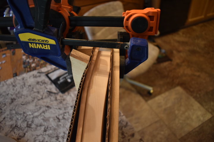
Using the template with the neck pocket as the bottom clamping caul and only half a bazillion clamps and cauls (in reality, probably more like 4), clamp the top down at the arm cut location.

Start at the curves and move to the middle as you put on clamps and make sure it’s completely closed all the way along the edge. Do not forget to use the cardboard shims and some angled cauls on the top because the clamps WILL dent the wood otherwise.

Wipe off any excess glue.
Arm cut bend glued and
                clamped

31

After it’s completely dry, dampen the top, let it dry, then sand it back to 220 grit (unless, of course, you’ve scratched or dented it, in which case you need to do the 60, 120, 220 sequence to remove said marks).

Use a dark stain on the top surface. I
f you are going for blue or purple or some other dark color I recommend using black - usually 2 or 3 coats. If you want something lighter you can use a darker shade of the color you’re going for or a complementary color and keep sanding back and staining to get nice depth of color. Check YouTube for a bunch of alternatives.
 
The best thing to do to get this right, and avoid a bunch of re-sanding and re-staining, is to test on scrap pieces of the top. When you get your colors right, go for it.
Top stained black

32

After the stain is dry sand it with 320 grit to create contrast between hard and soft grains (to taste - check YouTube).

The reason I go ahead and do the dark stain before I rout back the edges is that, no matter how careful you are, when you sand it down to get the contrast you will always take off too much at the edges. With 1/4” or a little more hanging off the sides it doesn’t matter because it will be cut away.

More recent lessons - get the body completely cut before you start staining. Leaving the edges doesn't make much difference and you won't have to be super careful when routing it to avoid dinging the top.
Top dark stain
                sanded back for contrast

33

Use the band (or scroll, or jig) saw to cut the top plate as close to the body edge as you can get it, then use a bottom bearing flush trim bit (from the top) to rout the top edges back to the body blank. Clean up the sides with 220 grit and elbow grease. If you scratch anything, clean it up.

I've just recently found the Robo-Sander flush trim drum sander. You can use one of these with 150 grit to get the overhang down to about a millimeter prior to flush trimming with the router. That really limits the chance of tear-out.

IMPORTANT NOTE: If you used a side jack instead of a Strat jack watch out for the jack hole as the wheel may go into it while trimming the top.

Using the body template (and, of course, clamps and double-side tape), rout the neck pocket. Be very careful young Padawan - if you make it too deep or too long you will be screwed worse than Jar Jar Binks at a Star Wars fan convention.
Top edges
                cleaned up and neck pocket routed

34

Put the neck in the pocket and check the locations of the bridge and pickups (don’t trust the template for this, it should be right but - check and double-check). Adjust it to where it needs to be then drill the holes for the neck screws.

Screw the neck in place and then check the location of the bridge again.
Hint: put a straight edge on each side of the neck and draw lines on the top from the neck to well past the bridge area. This will allow you to center the bridge in relation to the neck.

I've seen advice on the web and elsewhere saying that you should place the center of the saddle adjustment area at the scale length (normally 25 1/2" but in my case 24 3/4") from the nut. This is very bad advice. Physics tells us that a
string with no diameter (i.e. an imaginary, perfect string) would need the saddle location to be exactly the scale length away from the nut. Since all strings have some diameter, it follows that every saddle will end up (after intonation) farther away from the nut than the scale length. The larger the string, the farther from the nut that the saddle needs to be. Therefor, the high E string saddle, adjusted as far toward the nut as it will go, should be almost exactly the scale length from the body side of the nut. Of course, it will also end up just a bit farther away after intonation. This gives you the most adjustment area for all of your strings. If we were using a tune-o-matic style bridge we would actually angle it back on the bass side to get more adjustment room for the low strings.

With the neck in place, determine the bridge location, based on the above measurement of the high E string saddle and the two lines you marked, and mark it.

Mark the six through-body string holes using the bridge, remove the neck, then drill them (usually 1/8" bit) using the template (it’s a little tricky to line up but make sure you get it right). Hint: make sure that you don’t change the angle of the body in relation to the drill press when drilling the holes - no matter how well you think you have the table leveled, it won’t be exact.

Mark and rout the pickup cavities and the Strat jack plate hole.

Drill the holes for the volume, tone, and Les Paul style switch (use brad point or forstner bits to avoid tear-out). After they are drilled, check them to make sure that the pots and switch fit, then shield the open areas inside the control cavities (including around the Strat jack plate hole).

Top with
                pickup cavities and jack hole routed

35

Line the string retainer template up with the holes you just drilled through to the back of the body and drill the holes for the string retainers (ferrules). Use brad point or forstner bits!

At this point you can also round over the control cavity edges and the edges of the cover plates. Don't overdo it, just a little bit of rounding goes a long way. Keep putting them in to see how they look. You'll also notice, in the picture to the right, that the plates are slightly recessed from the back. Since the plates are removed with pressure I figured it might be better not to have anything accidentally pressing on them. Honestly, I don't think it matters, those magnets are incredibly strong for their size.
Back with string retainer grommet holes drilled

36

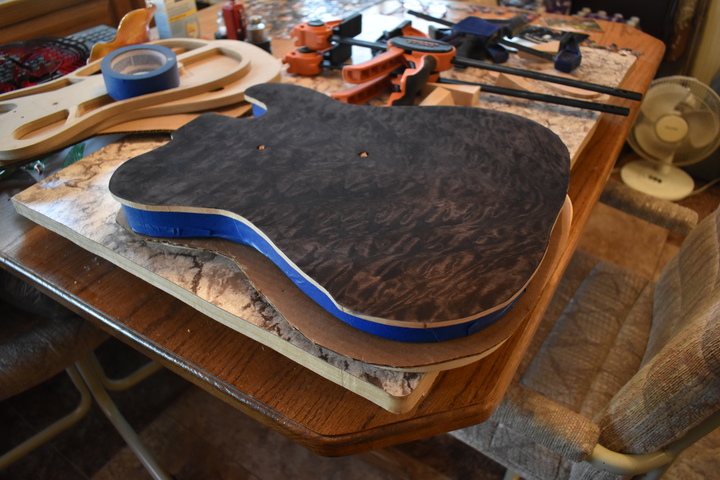
Stain the top ala Dan Erlewine (read through the entirety of https://www.stewmac.com/How-To/Online_Resources/Learn_About_Instrument_Finishing_and_Finish_Repair/Finishing_a_Blue_Guitar_A-BLUEGUITAR_1.html incuding parts 2 and 3). I would follow Dan’s advice on this, with the exception of the f-hole (note that we haven’t routed it yet - we're going to do that later).
Top stained, sides masked

37

Now we need to rout the f-hole. As far as I can tell, there are no Dremel flush trim, top bearing, router bits so we have to use part of the shank of the 1/8" upcut (or regular) router bit against the template side to guide it.

The upcut bit is 1 1/2" long with 5/8" of cutting surface. The template is, nominally, 1/2". So, in order to get most of the cutting surface below the template without cutting the template, you'd need to cut, at best, about 1/2" below the template. That's a very bad idea, especially when trying to cut through maple.

What we need is a 1" thick template. Since we still only need about 1/2" of guiding surface, only the top level of the template needs to be accurate. The way I dealt with this was to cut a rough template, slightly larger than the f-hole, in two cardboard guitar cutouts and a piece of 1/4" plywood. I double-side taped them together in this order, from the bottom up: cardboard, 1/4" plywood, cardboard, 1/2" template. Double-side tape this to the top, then clamp it in place. Rout the outline of the f-hole. The first cut should be as shallow as possible. Go deeper until you run out of shaft then unclamp the templates, remove the lower cardboard and the 1/4" rough template, then, very carefully, double-side tape and clamp the 1/2" template and cardboard back in place (EXACTLY in place), then continue routing down until you go through the maple top.

This will give you an f-hole with an unstained inner edge. Ta da, f-hole faux binding with no muss, no fuss, and no bother!
f-hole routed

38

Mask the faux binding (and probably part of the top just to be safe) and stain the sides and back (See Dan's tutorial referenced above).

I use Prostripe pinstriping tape to mask it. You can find that at most auto parts stores (I found it at Auto Zone).

Do the faux binding as per Dan's tutorial. Also, do the faux binding in the f-hole. This is a bit trickier and may require you to make little sanding/filing tools to get in there. I have heard that popsicle sticks work nicely but they won't work well in the round parts. I used a couple of tiny files (one flat, one round) with sandpaper double-side taped to them.
Sides and back stained, faux binding completed

39

Make a handle for the neck pocket, attach it, and spray on 3 light coats of Minwax High Gloss water-based poly (if you don’t do this first, the wipe-on will smear the water-based stain). When it's dry, use 0000 steel wool to smooth it out just a bit.

More recent technique - wipe down the stained body with Naphtha or alcohol, coat it with 3 very thin coats of Tru Oil, then wait a couple of days before wiping on the water-based poly. Why? Because Tru Oil increases the chatoyancy (cat's eye effect) of the figured maple. You can see from the picture on the right that the faux binding is rather bland. With Tru Oil it looks more like marble or mother of pearl in places. It will be just slightly darker than the poly finish but it's worth it. In addition, you don't have to find somewhere to spray it.
Body
                with first spray-on coats of poly

40

Spend the next week or so wiping on about 15 to 20 extremely thin coats of Minwax High Gloss Wipe-On poly (you can do about 3 or 4 coats a day). Don’t sand between coats unless you absolutely have to. If you wipe it on thinly enough it should be smooth. Check every coat when you put it on for runs or drips and try to wipe them out. If you miss one or more, figure out how to fix them (usually with 600 grit sandpaper) and re-coat.
Top with
                20 coats of wipe-on poly

41

Wait a few days to a week for the poly to completely harden then wet sand with 1500, 2000, 2500, and, maybe, 3000 grit sandpaper. Polish out (by hand) with Meguiar's Rubbing Compound followed by Meguiar's Polishing Compound. If needed you can follow up with some swirl remover.
Top, sanded and
                polished

42

Shield inside the pickup cavities and around and under the jack plate.


Cavities shielded

43 - 100

Et voila! Fini!

Wait... just kidding... now you have to mount all the hardware, wire the switch, pots, pickups and jack together (oh joy, soldering!), check the switch, pots, and pickups (then probably un-solder and do it again correctly), mount the neck, put in the tuners, slot the nut, set the intonation, set the action... did I forget anything? Probably!

Have fun!
Stelekaster
                front close-up